Casio MT-240 schematic and walkthough
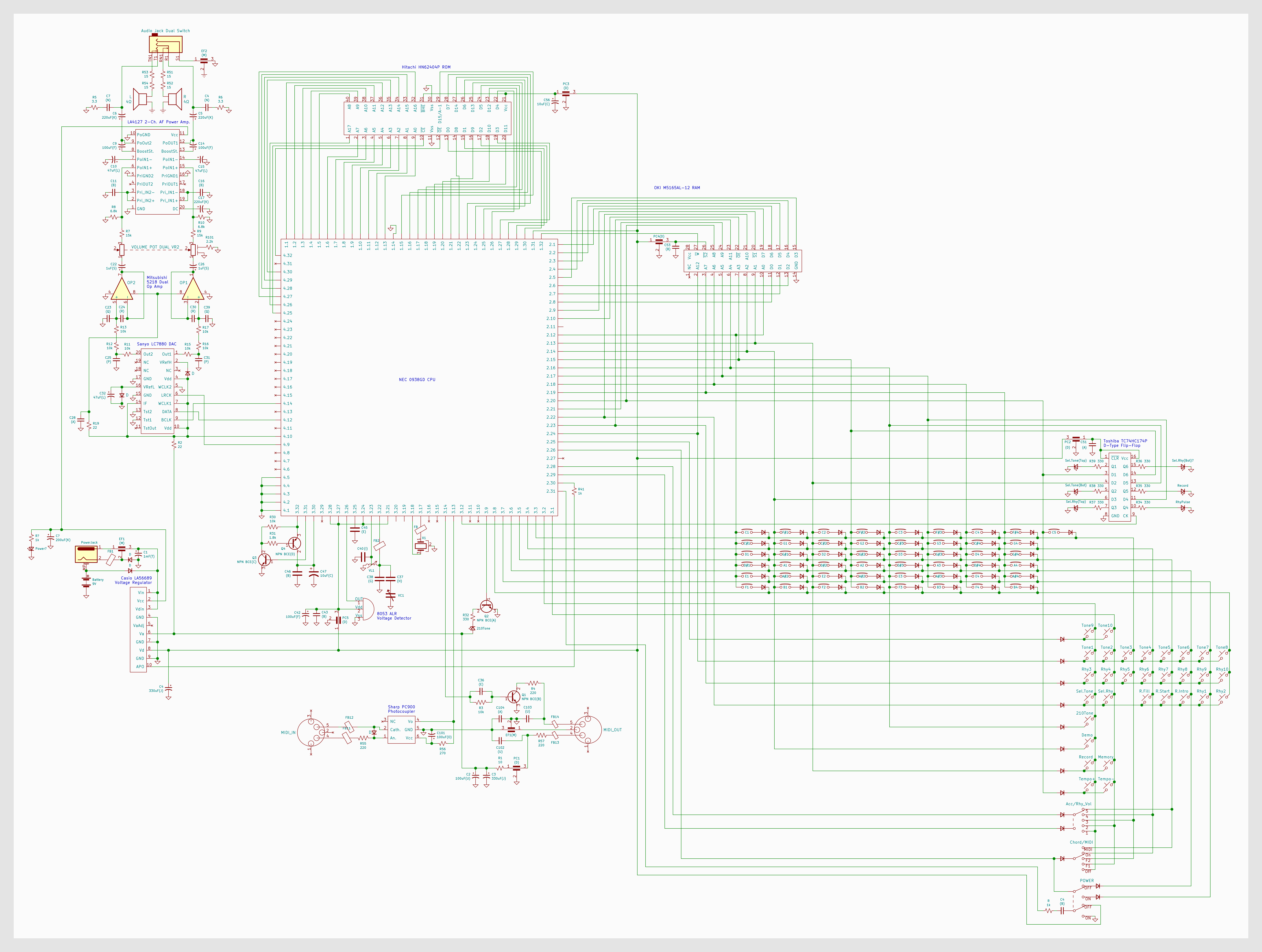
Summary
The MT-240 regulates and distributes power to the CPU and other ICs. crystal oscillator sets the clock speed of the CPU. The CPU repeatedly scans for key and button presses through keyboard and button matrices. An LC tuning circuit determines the base frequency from which note pitches are derived. When the keyboard is played, synthesis programs begin and data is exchanged between the ROM and CPU until the final waveform is assembled and encoded in PCM. The DAC synthesizes the PCM signal into an analog waveform, which is amplified in stages until it finally reaches the speakers or external headphones. Additionally, the synth can send and receive midi data, record a short sequence of key presses in RAM, and a flip-flop turns on LEDs. There are a few unsolved mysteries.
Power-On
Power-On is accomplished in two stages. Plugging the keyboard in with an AC adapter or batteries begins power supply to the voltage regulator chip, which distributes power to the other chips. But the synth cannot be played yet. The 'POWER' switch must be activated to enable the CPU. Meanwhile, the voltage detector chip regulates the voltage to the CPU so that it remains as stable as possible and does not exceed a threshold.
Keyboard & Button Matrices
When you press a key, you are pressing a momentary switch that forms an electrical connection between two pins on the processor, organized into rows and columns on a matrix. For example, pressing the 'A4' key corresponds to row 4, col 11. Diodes in series with each key allow the processor to distinguish between individual keys. The Tone and Rhythm buttons also work this way, organized in a separate matrix.
There are some empty spaces in both the keyboard and buttons matrices, which correspond to some hidden functions, ones that the processor was designed to handle but were never implemented for the user. 1. A hidden upper octave; the keyboard matrix actually can give 61 combinations (5 octaves), but only 49 keys are on the keyboard. 2. 10 additional 'Tones.'
Tones
There are 20 preset Tones (30 if the ten hidden tones are included), each with unique synthesis parameters. The unique data for each parameter of each Tone is fetched by the CPU from the ROM. Each parameter in a Tone (the attack, decay, sustain, release, pitch, and others) exist separately until it is assembled by the CPU into its final PCM form.
As the pitch increments for each key up, the timbre of the note starts to change and subtle adjustmentments are needed to maintain the sense of synthesizing a realistic instrument. So the user does not notice, there is often a subtle change in parameter from one note to another.
LC circuit
Each note get its frequency derived from a fixed frequency determined by the oscillating frequency of the LC circuit. The processor multiplies the base frequency by 2
ROM and CPU
Upon key press, the CPU and ROM start a rapidly repeating cycle with 3 general steps; 1.the ROM sends an address via 18 parallel Address(A) lines to the ROM chip; 2.the ROM then returns corresponding data back to the CPU across 16 parallel Data(D) lines; 3.the data is operated upon, slowly assembling the final PCM waveform. This happens extremely quickly and repeats many times.
Xtal Clock
The Crystal Clock oscillates at a frequency which determines the speed at which these cycles happen, which sonically affect things such as tremolo, vibrato, glisses.
DAC and Amplification
Once the final PCM waveform is assembled, it is sent serially to a DAC, which converts the data into an ongoing analog signal. This signal is pretty quiet. First, it is amplified by an op amp system to a level that is only a little bit louder: to act as a buffer and so that it can be adjusted by a volume slider within reasonable margins. Then, it is put through a power amplifier IC where it reaches final line level.
Speakers or Headphones
Finally, the signal passes by the on-board speakers. Alternatively, if something is plugged into the headphone jack, it bypasses the high impedance speaker line.
MIDI, RAM, Flip Flop, Mysteries
The CPU can also handle a small and seemingly not very useful MIDI system with a photocoupler IC. The Flip-Flop controls the LEDs, which indicates settings, toggled digitally by the CPU. The RAM can be used to record a short sequence of key presses. Last, the mystery: a transistor system of unknown function.